In short: A 2-wire lighting system has only a permanent live and a switched live at the wall switch. A 3-wire system has a neutral there as well. Most UK homes are 2-wire, so check which you have before you choose a smart switch, dimmer or module, because many smart devices need a neutral to stay powered.
Who this guide is for
- You want to fit a smart switch, dimmer or in-wall module and need to know if your wiring suits it.
- You have opened a switch or ceiling rose and want to understand what each wire does.
- You are an installer planning smart lighting on 1-way, 2-way or intermediate circuits.
Safety first. Mains wiring can kill. It must be done by a competent person, with the circuit isolated and proved dead, and it must comply with local regulations (in the UK, BS 7671 and the Building Regulations). This guide explains how circuits work so you can choose the right product. It is not a step-by-step wiring instruction. If you are not sure, use a qualified electrician.
What is a lighting circuit?
A lighting circuit is a cable run from your consumer unit (fuse box) that feeds a group of lights and their switches. A typical UK home has one for each floor. Each is protected by its own breaker or fuse, usually 6 amp in a modern consumer unit.
Every light needs two things to work: a live that brings power in and a neutral that takes it back. The wall switch sits in the live side and simply breaks or joins it. An earth runs alongside for safety.
Cable for lighting circuits
UK lighting circuits are normally wired in flat "twin and earth" cable, 1.0 mm² or 1.5 mm², which has two insulated cores plus a bare earth. Between 2-way switches you will find "3 core and earth", which has three insulated cores plus the earth.
| Wire | What it does | Colour now | Older colour |
|---|---|---|---|
| Permanent live | Live all the time, whether the light is on or off | Brown | Red |
| Switched live | Runs from the switch to the light. Live only when the switch is on | Brown, or blue with a brown sleeve | Red, or black with a red sleeve |
| Neutral | The return path from the light | Blue | Black |
| Earth | Safety connection. Carries no current in normal use | Green and yellow sleeve | Green sleeve, or bare |
The brown and blue colours came in during the mid-2000s. Homes wired before then use red and black, and many homes have a mix. In 3 core and earth cable the cores are brown, black and grey (older cable: red, yellow and blue). Other countries use different colours. In North America, for example, live is usually black and neutral white.
What is a switched live wire?
A switched live is the wire that carries power from the switch to the light. It is only live when the switch is on. The permanent live is the wire that brings power to the switch and is live all the time.
So a simple light switch has two live wires on it: permanent live in, switched live out. Neither of them is a neutral.
What colour is a switched live?
This catches many people out. The cable to a switch is usually ordinary twin and earth, so one core is brown and the other is blue. The blue core is being used as the switched live, not as a neutral. It should be marked with a short brown sleeve or brown tape at each end to show this. In older wiring it is a black core with a red sleeve.
The sleeve is often missing. Never assume a blue or black wire at a switch or ceiling rose is a neutral. In 2-gang and 3-gang switches, black and grey cores with brown sleeves are also switched lives.
2-wire lighting systems (no neutral at the switch)
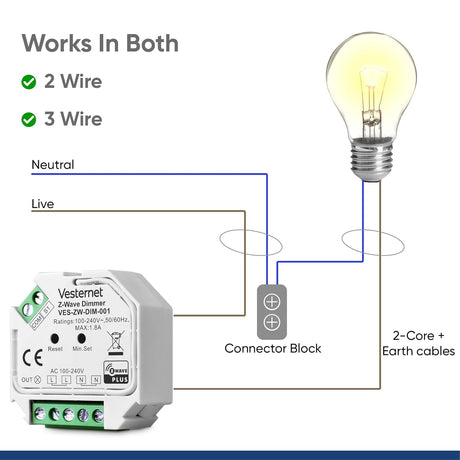
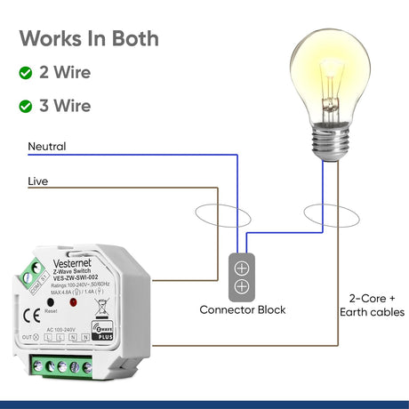
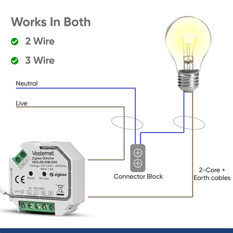
This is the most common arrangement in the UK and much of Europe. It is called 2-wire because only two working wires reach the switch: permanent live and switched live. The earth is there too, but it plays no part in switching, so it isn't counted.
In most UK homes the power "loops in" at the ceiling rose. The live and neutral run from light to light across the ceiling. At each rose, one cable drops down the wall to the switch and back. The neutral stays up at the ceiling and never goes near the switch.
How a light switch with 2 wires is wired
A one-way switch has two terminals, usually marked COM and L1. The permanent live goes to one and the switched live to the other. On a simple one-way switch it works either way round. The earth core is sleeved green and yellow and goes to the earth terminal in the back box, and to the switch plate too if it is metal.
If your switch has only two wires plus an earth, you have a 2-wire system. That is normal, and it is the reason a smart device at that switch has no neutral to use.
Junction box circuits
Some homes, often older ones, use junction boxes above the ceiling instead of looping in at each rose. The feed, the switch cable and the cable to the light all meet in the box. The result at the switch is the same: permanent live and switched live, no neutral.
3-wire lighting systems (neutral at the switch)
In a 3-wire system the supply loops in at the switch instead of the ceiling. One cable brings live and neutral to the switch back box. A second cable takes switched live and neutral up to the light.
The neutral is not connected to an ordinary switch. The two neutral cores are joined together in a connector at the back of the box and carry on to the light. What matters is that a neutral is available at the switch for a smart device to use.
This layout is less common in older UK homes. It is found more often in recent new builds and rewires, because the wiring regulations (BS 7671) now ask installers to consider providing a neutral at each switch position for electronic switches.
Wiring a ceiling light with 2 wires or 3 wires
The number of wires at the light causes as much confusion as the switch. There are two separate questions: how many wires the light fitting has, and how many cables arrive at the ceiling.
A light fitting with 2 wires
Brown (live) and blue (neutral) only. The fitting is "double insulated" (Class II, marked with a square inside a square) and has no earth terminal. The earth core in the ceiling cable is still kept. It is sleeved and parked in its own connector, never cut off.
A light fitting with 3 wires
Brown (live), blue (neutral) and green and yellow (earth). This is a Class I fitting, usually metal, and it must be earthed. The three wires are live, neutral and earth. None of them is a "spare".
Connecting a 3-wire light to a 2-wire supply
If the fitting needs an earth and the ceiling cable has one, the fitting's earth joins the circuit earth. If the ceiling cable has no earth at all, which is the case on some lighting circuits installed before the mid-1960s, a fitting that needs an earth must not be used there. Choose a double insulated fitting or have the circuit upgraded by an electrician.
Two live wires in a light fitting, or three cables at the ceiling
A loop-in ceiling rose normally has three cables: the feed in, the feed out to the next light, and the cable to the switch. That means several browns (or reds) and several blues (or blacks) in one place, and not all of the same colour do the same job.
- The lamp connects to two things only: the switched live and the neutral.
- The permanent lives are joined together on the loop terminals and carry on to the next light. They do not connect to the light fitting. This is why you can find "two live wires" at a light.
- One blue or black core belongs to the switch cable. It is the switched live. If it is put with the neutrals when a fitting is changed, the breaker trips or the light stays on. This is the most common mistake when replacing a ceiling rose with a new fitting, and the reason to label every wire before anything is disconnected.
- A ceiling point with one cable (two cores and an earth) is simpler. It carries switched live and neutral only, usually because the joints are in a junction box or at the switch.
How do I know which system I have?
Assume 2-wire unless you can prove otherwise, especially in a UK home that has not been rewired recently.
- Look at the age of the wiringOlder UK homes are nearly always 2-wire. Recent new builds and rewires may have a neutral at the switch, but it is not guaranteed.
- Check what reaches the switchWith the circuit isolated, a competent person can look in the back box. One cable, with every core connected to the switch, means 2-wire.
- Look for joined neutralsTwo or more blue (or black) cores joined in a connector block and not connected to the switch suggest a 3-wire system.
- Have it confirmedColours can mislead. A switched live with a missing sleeve looks like a neutral. Ask an electrician, or another competent person with proper test equipment, to confirm what each wire is before you buy.
Each switch can be different. A hallway may be 2-wire while a new extension on the same floor is 3-wire, so check every position you plan to change.
How do I know which products will work with my system?
Every smart switch, dimmer and module needs a little power all the time, so it can listen for commands when the light is off. A neutral gives it that power directly. Without one, the device has to draw a tiny current through the lamp instead. That is why the product choice is narrower on 2-wire circuits.
Product pages state whether a device needs a neutral. Look for "no neutral required", "2-wire" or "works with or without neutral". If it only says "neutral required" or "3-wire", it will not work at a 2-wire switch.
| Device | 2-wire (no neutral) | 3-wire (with neutral) |
|---|---|---|
| In-wall dimmer module | Many models work. A minimum load applies and a bypass may be needed | Yes |
| In-wall switch (relay) module | Only models designed for it, often with a bypass | Yes, all models |
| Replacement wall switch or dimmer | Only "no neutral" versions | Yes |
| Blind, shutter and heating modules | No. These need a neutral | Yes |
| Smart bulbs and battery wall controllers | Not affected by switch wiring | Not affected by switch wiring |
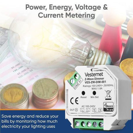
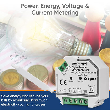
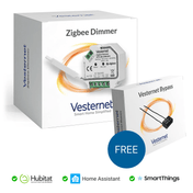
 In-wall dimmer moduleFits behind the switch. Many work with or without a neutral.
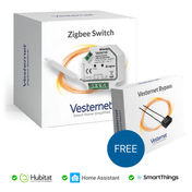
 In-wall switch moduleOn and off control. Most need a neutral, some do not.
 Replacement wall switchSwaps the whole switch. Sold in neutral and no-neutral versions.
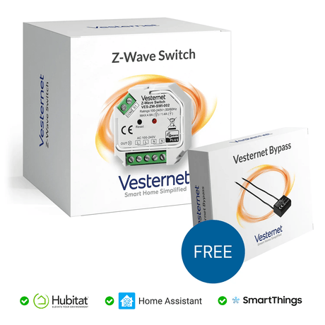
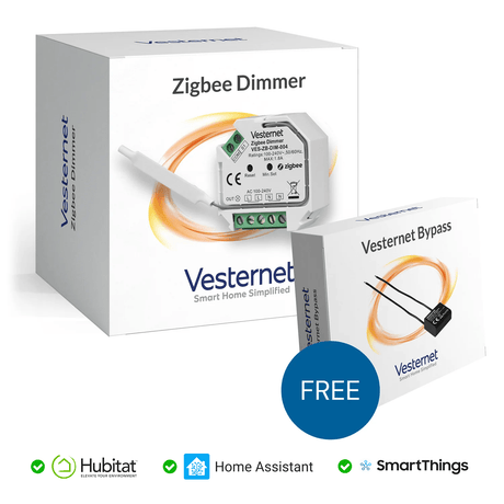
 BypassFitted at the light to stop low-load LEDs flickering or glowing.
Can I use a smart relay or switch without a neutral?
Sometimes. For years the answer was no. A relay is a simple on/off contact, and when it opens, no current flows, so the electronics lose power. Dimmers could manage without a neutral because they never fully break the circuit. They let a trickle of current through the lamp, too small to light it, and run on that.
Some newer switch modules and wall switches use the same trick, so no-neutral on/off control is now possible. The rules of thumb are:
- With a neutral, any switch, relay or dimmer will work, and there is usually no minimum load to worry about.
- Without a neutral, you need a device that says it supports 2-wire or no-neutral use. A dimmer is often the easiest answer, and many can be set to simple on/off if you don't want dimming. It is still a dimmer, so use dimmable lamps.
- Loads that are not lights (fans, pumps, motors, heaters) should be switched by a relay with a neutral.
There is one more option an electrician may suggest. A neutral is always present at the light. Where a permanent live is there too, as in a loop-in ceiling rose, a module can sometimes be fitted at the ceiling in a suitable enclosure instead of behind the switch.
LED flicker, glow and the bypass
A no-neutral device depends on a small current leaking through the lamp. Old filament bulbs passed it without any visible effect. A modern LED load can be so small that the leak is enough to make the lamps glow faintly when off, flicker, or flash every few seconds. The smart device may also drop off the network because it cannot draw enough power.
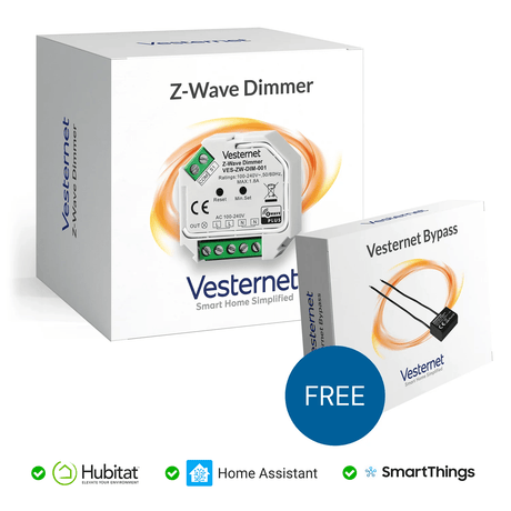
Every no-neutral device has a minimum load. One or two LED lamps are often below it. The fix is a bypass: a small component wired across the light, between switched live and neutral. It gives the trickle current an easier path, so the lamps stay dark and the device stays powered.
A bypass is fitted at the light fitting (or the first fitting in a group), not at the switch. Use the bypass recommended for your dimmer or switch, and check the minimum load on the product page.
2-way and intermediate switching
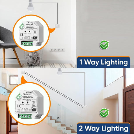
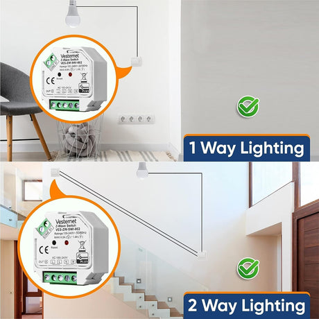
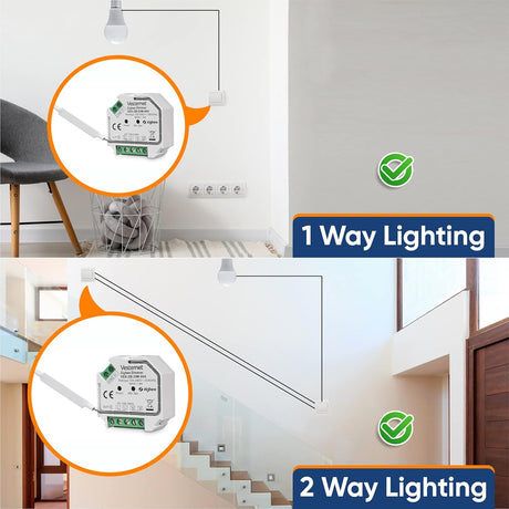
A 2-way circuit lets two switches control one light, such as the top and bottom of the stairs. Each switch has three terminals: COM, L1 and L2. In the standard UK method, a 3 core and earth cable links the two switches terminal to terminal. This is the "3 wire connection" between 2-way switches.
Intermediate switching adds a third (or fourth) switch in the middle, for a long landing or a room with three doors. The intermediate switch has four terminals and is wired into the link between the two 2-way switches. Each press swaps the connections over.
Some homes use other methods: a 2-core link between the switches with the live at one end and the switched live at the other, or all cables meeting in a junction box at the ceiling. The effect is the same, but the wires at each switch differ, so the circuit must be identified before a smart device is chosen.
Fitting smart control to a 2-way circuit
You only need one smart device for each light, however many switches control it.
Module plus existing switches
The module goes at the switch that has both permanent live and switched live (switch A above), or at the light. The linking cable is reused to carry the other switch's signal back to the module's switch input. Both wall switches keep working.
Module plus a wireless controller
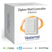
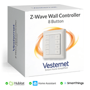
The module or smart switch replaces one switch. The other is replaced by a battery wall controller that needs no wiring and talks to the module over Z-Wave or Zigbee. Useful when the old link cable is in poor condition or you want an extra switch position.
Smart wall switches
Most replacement smart switches and dimmers cannot be dropped into a conventional 2-way circuit as a pair. They are linked wirelessly instead, or sold with a matching companion switch. Check the product page.
Without a neutral, the same rules apply as for a single switch: use a no-neutral device, mind the minimum load and add a bypass if the LEDs misbehave.
Using your existing switches with a module
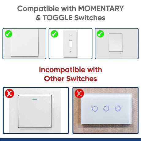
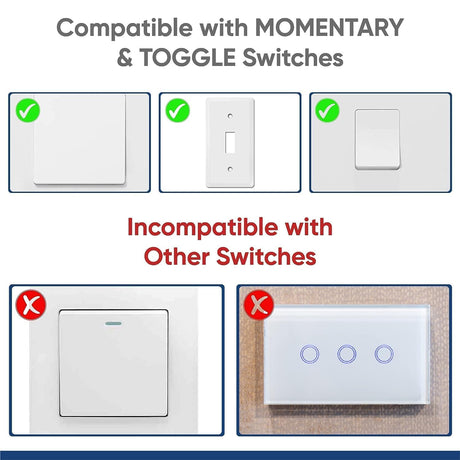
An in-wall module has a switch input, so your wall switch keeps working. Most modules accept two kinds of switch, set in the module's settings:
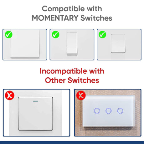
- Toggle switches (the normal rocker that stays up or down). Fine for on and off. With a dimmer module, each flick turns the light on at its last level or off.
- Momentary switches (also called retractive or push-to-make, they spring back). Best for dimming: tap for on and off, hold to dim up or down.
- Centre-off retractive switches (up and down, resting in the middle) suit some dimmers and blind controls. Not every module supports them fully.
Two things should not be wired to a module's switch input: a conventional rotary or push dimmer, which fights the module's own dimming, and electronic or touch switches with indicator lights, which most modules cannot power. More on choosing between modules, wall switches and bulbs is in Smart light switches, dimmers and modules.
Planning a smart lighting installation
- Survey each switchNote 1-way, 2-way or intermediate, the number of gangs, and whether a neutral is present.
- Check the loadAdd up the lamp wattage on each circuit and note whether the lamps are dimmable LEDs.
- Check the spaceModules need room behind the switch. Shallow UK back boxes (16 mm or 25 mm) are often too tight. A 35 mm or 47 mm box is the usual answer.
- Choose the device and controllerPick the module or switch that suits the wiring, then check it works with your hub.
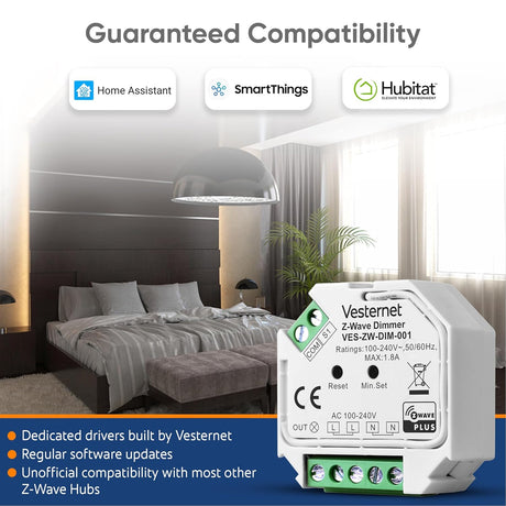
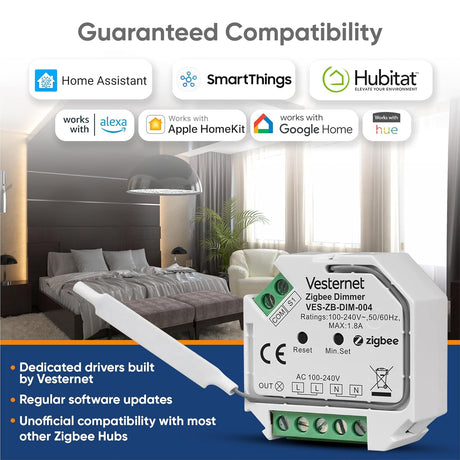
Smart modules work with all the main controllers: Hubitat, Homey Pro, Home Assistant, the Aeotec Smart Home Hub (SmartThings) and Fibaro Home Center. Support varies by device, so see Will it work with my system? and Choosing a smart home controller.
Wiring notes for each circuit type
These application notes show worked examples of an in-wall dimmer module in each common UK circuit, with toggle and momentary switches. The principles apply to most modules, but always follow the wiring diagram in your own device's manual.
| Circuit | What it is | Without neutral | With neutral |
|---|---|---|---|
| Standard 1-way | One switch, one light | Wiring note | Wiring note |
| Standard 2-way | Two switches linked by 3 core and earth | Wiring note | Wiring note |
| 2-way, 2-gang | Two lights, each with 2-way switching, on 2-gang plates | Wiring note | Ask us |
| Intermediate (3-way) | Three or more switches for one light | Wiring note | Wiring note |
| Alternate 2-way | Two switches linked by a 2-core cable | Wiring note | Wiring note |
For fitting a module into a back box, see physically installing a dimmer or relay module.
Do I need an electrician?
All electrical work in a home must be safe and must meet the wiring regulations, whoever does it. In England and Wales, Part P of the Building Regulations applies to all of it. Some jobs must also be notified to building control or done by a registered electrician. In England these are a new circuit, a replacement consumer unit, and additions or alterations close to a bath or shower or in a room with a pool or sauna. Wales has a longer list, which includes extending a circuit in a kitchen or outdoors. Scotland and Northern Ireland have their own rules.
Replacing a switch or adding a module to an existing circuit is not usually notifiable in England. In Wales, check first if the work is in a kitchen or outdoors. Either way it still has to be done competently and tested. If you cannot confidently and safely identify permanent live, switched live and neutral, this is a job for an electrician.
What you'll need
- In-wall dimmer modules and switch modules
- Smart wall switches and dimmers
- Battery wall controllers for extra switch positions
- Accessories, including bypasses