Function Description and Indication
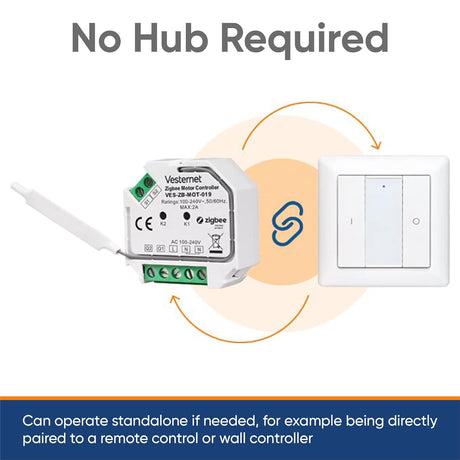
Set the Z-Wave controller to association mode. Press the link key three times within 1.5 seconds to enter association mode; the detector will beep with each press. The device supports two association groups (Group 1 and Group 2), explained in the Z-Wave grouping section on page 4.
Inclusion means adding a node ID from a Z-Wave controller, while exclusion means removing it. The controller will indicate whether the process is successful or not.

Installation Guidelines
The Motion Detector can be mounted on a wall or ceiling. When selecting a location, avoid placing it facing windows, fans, air conditioners, or direct sunlight. Do not install it above or in front of heat sources such as radiators, boilers, or fireplaces. Ensure the detector is positioned where the detected light reflects actual ambient illumination and avoid shadowed areas. For optimal coverage, mount it so that an intruder’s movement crosses the detection pattern rather than moving directly toward the detector (see Figure 1). For best performance, place the detector facing the entrance.

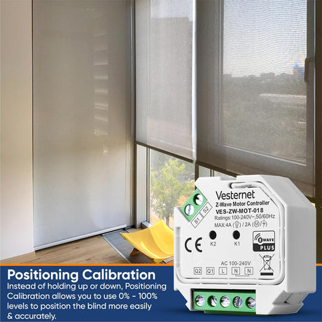
Coverage Range Adjustments
The detector comes with two lens covers. The wall-lens cover (Figure 6a) is for wall-mounted installation, while the ceiling-lens cover (Figure 6b) is for ceiling-mounted installation. Coverage range adjustments apply only to the ceiling-lens cover, so select the correct lens cover before mounting.
The shading cap has 12 segments, each covering a 30-degree detection angle (Figure 6c). Follow the grooves on the cap, cut it to the desired size, and place it onto the ceiling-lens cover (Figure 6d). Remaining segments can be used to block undesired detection areas.